
|
|
|
|
|
|
|
|
|
|
||||||||
|
|||||||||
|
Product
Tools, Drivers, etc |
GESBC-9G20wPre-built Binary Images Pre-compiled boot strap code for standard 32MB SDRAM board. Pre-compiled U-Boot image for standard 32MB SDRAM board. Pre-compiled Linux 3.6.9 kernel image. RAM disk image(OABI). Batch file to be used with Atmel SAM-BA to load images. TCL script to be used with Atmel SAM-BA to load images. Pre-compiled boot strap code for standard 32MB SDRAM board. Pre-compiled U-Boot image for standard 32MB SDRAM board. Pre-compiled Linux 3.6.9 kernel image. RAM disk image(OABI). Batch file to be used with Atmel SAM-BA to load images. TCL script to be used with Atmel SAM-BA to load images.
Getting StartedThe GESBC-9G20w comes from factory with Linux pre-installed and ready to run.
When GESBC-9G25w powers up the system boot message will be displayed on the terminal screen.
Source Code, Patches U-Boot 2013.4 source patch for GESBC-9G20w.
Board Connection Diagram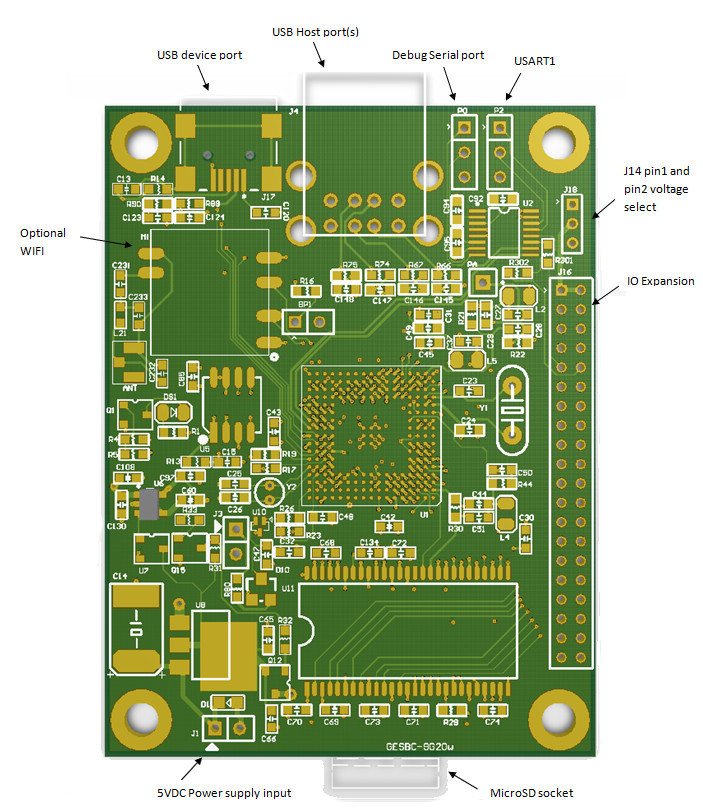
Power ConnectionThe GESBC-9G20u Single Board Computer requires regulated 5V DC. The power supply should have minimum 300mA capacity.
JTAG ConnectionThe GESBC-9G20w supports JTAG interface. The JTAG connection is on the back side of the PCB with a 2x5 surface mount header (unpopulated from factory). The JTAG signal arrangement is shown in the following table
Serial Port connectionThe GESBC-9G20w has a debug serial port that can be connected to desktop system to debug/monitor system. The debug serial port communication settings are 115200,8,N,1. The USART1 Tx and Rx signals are routed to both the on-board RS-232 driver chip and I/O expansion port. By removing the R301 and R302 the USART1 can be disconnect from the RS-232 driver chip and be exclusively available on the I/O expansion port.
I/O ExpansionThe GPIO expansion port on the GESBC-9G20u consists of 36 configurable signal line. Each line can be configured as general purpose I/O or many other peripheral functions provided by the versatile AT91SAM9G20 processor core. The schematics below shows a simple peripheral expansion board expands the GESBC-9G20u with 4 RS-232 port (2 with hardware handshake) and 1 CAN bus port, The CAN bus transceiver MCP2515 connects to the SPI bus of the GESBC-9G20u through the GPIO header J16 on the GESBC-9G20u. GPIO line PB12 and PB 13 are used as the reset control of the MCP-2512 and interrupt request. The MCP2515 connects to the 3.3V power rail to ease the interface to the 3.3V AT91SAM9G20 GPIO logic circuit. The CAN bus signal driver MCP2551 operates at 5V power rail to drive the high voltage CAN bus signal. A diode clamps the MCP2551 output to 3.3V for the CAN bus transceiver MCP2515. Three RS-232 driver chips are used to facilitate four RS-232 serial port. RS-232 port 1 and RS-232 port 2 have RTC and CTS hardware flow control signals. The RS-232 port 3 and RS-232 port 4 are 3-wire RS-232 ports. The individual I/O signal definition on the I/O expansion header is shown in the diagram below. 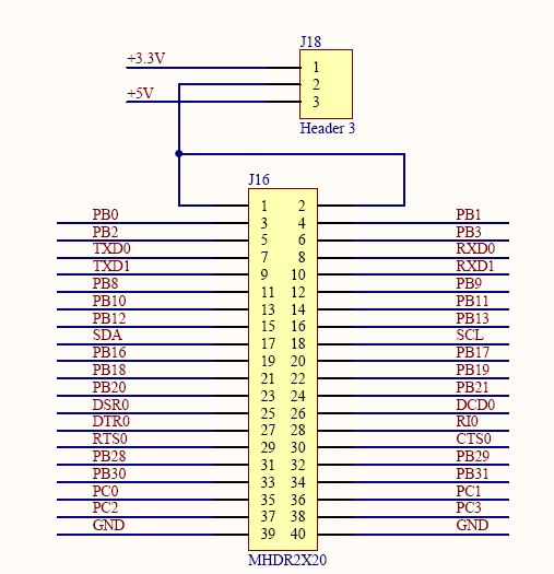
Factory Installed Software and FLASH memory AllocationThe GESBC-9G20w has basic software/firmware installed from the factory for demonstration purposes. The factory installed software includes boot strap code, U-boot, Linux kernel, and a RAM disk image. The U-boot is configured to load the kernel image and the RAM disk image from the FLASH memory and using the RAM disk as the root file system. The GESBC-9G20w is configured to boot from on-board SPI FLASH. The factory default storage map is shown in the following table,
Modify Atmel SAM-BA to Load Factory ImagesThe GESBC-9G20w uses 16 bit memory bus. The Atmel SAM-BA library file at91sam9g20-ek.tcl in the C:\Program Files\ATMEL Corporation\sam-ba_2.12\tcl_lib\at91sam9g20-ek directory must be modified to set the memory bus width from 32 to 16.
    # Set bus width (16 or 32)
    variable extRamDataBusWidth 16
Using SD Card as Root File SystemThe GESBC-9G20w factory installed software uses RAM disk as root file system. User can change the root file system setting to SD card or USB drive by change the U-Boot bootargs environment variable setting. The following example demonstrates the SD card as root file system, set bootargs mem=32M console=ttyS0,115200 root=/dev/mmcblk0p1 rootdelay=5 saveenv
Sample Program Sample C program to generate PWM output on GESBC-9G20/GESBC-9G20u/GESBC-9G20w.
|
